Contents
- DIY drone: Lesson 1. Terminology.
- Do-it-yourself drone: Lesson 2. Frames.
- Do-it-yourself drone: Lesson 3. Power plant.
- Do-it-yourself drone: Lesson 4. Flight controller.
- Do-it-yourself drone: Lesson 5. Assembly.
- Do-it-yourself drone: Lesson 6. Performance check.
- Do-it-yourself drone: Lesson 7. FPV and distance.
- Drone with your own hands: Lesson 8. Airplanes.
Introduction
Now that you have selected or designed the UAV frame, motors, rotors, ESCs and battery, you can start choosing your flight controller. The flight controller for a multi-rotor unmanned aerial vehicle is an integrated circuit, usually consisting of a microprocessor, sensors, and input / output pins. After unpacking, the flight controller does not know which specific type or configuration of UAVs you are using, so initially you will need to set certain parameters in the software, after which the given configuration is loaded on board. Rather than simply comparing the currently available flight controllers, the approach we have taken here lists which elements of the PC are responsible for which functions, as well as aspects to look out for.
Main processor
8051 vs AVR vs PIC vs ARM: A family of microcontrollers that form the basis of most modern flight controllers. Arduino is based on AVR (ATmel) and the community seems to be focused on MultiWii as the preferred code. Microchip is the main manufacturer of PIC chips. It's hard to argue that one is better than the other, it all comes down to what software can do. ARM (like STM32) uses 16/32-bit architecture, with dozens using 8/16-bit AVRs and PICs. As single board computers become less and less expensive, next-generation flight controllers are expected that can run full-fledged operating systems such as Linux or Android.
CPU: Usually, they are multiples of 8 (8-bit, 16-bit, 32-bit, 64-bit), which in turn indicates the size primary registers in the CPU. Microprocessors can only process a set (maximum) number of bits in memory at a time (clock). The more bits the microprocessor can handle, the more accurate (and faster) the processing will be. For example, processing a 16-bit variable on an 8-bit processor is much slower than on a 32-bit one. Note that the code must also run with the correct number of bits, and at the time of this writing, only a few programs use code that is optimized for 32 bits.
Operating frequency: The frequency at which the main processor operates. It is also called "clock rate" by default. Frequency is measured in hertz (cycles per second). The higher the operating frequency, the faster the processor can process data.
Program / Flash: Flash is where the main code is stored. If the program is complex, it can take up a lot of space. Obviously, the larger the memory, the more information it can store. The memory is also relevant for storing in-flight data such as GPS coordinates, flight plans, automatic camera movement, etc. The code loaded into the flash memory remains on the chip even after the power is turned off.
SRAM: SRAM stands for Static Random Access Memory and is the space on the chip that is used for calculations. Data stored in RAM is lost when the power is turned off. The higher the amount of RAM, the more information will be “readily available” for calculations at any given time.
EEPROM: Electrically Erasable Programmable Read Only Memory (EEPROM) is typically used to store information that does not change during flight, such as settings as opposed to data. stored on SRAM, which may include sensor readings, etc.
Additional I / O ports: most microcontrollers have a large number of digital and analog input and output ports, on the flight controller some are used for sensors, others for communication, or for general input and output. These additional ports can be connected to RC servos, gimbals, buzzers and more.
A / D converter: If the sensors use an onboard analog voltage (usually 0-3.3V or 0-5V), the analog A digital converter must convert these readings to digital data. As with the processor, the number of bits that the ADC can handle determines the maximum accuracy. Associated with this is the clock rate at which the microprocessor can read data (times per second) to ensure that information is not lost. However, it is difficult not to lose some of the data during this conversion, so the higher the bit depth of the ADC, the more accurate the readings will be, but it is important that the processor can handle the speed at which the data is being sent.
Power supply
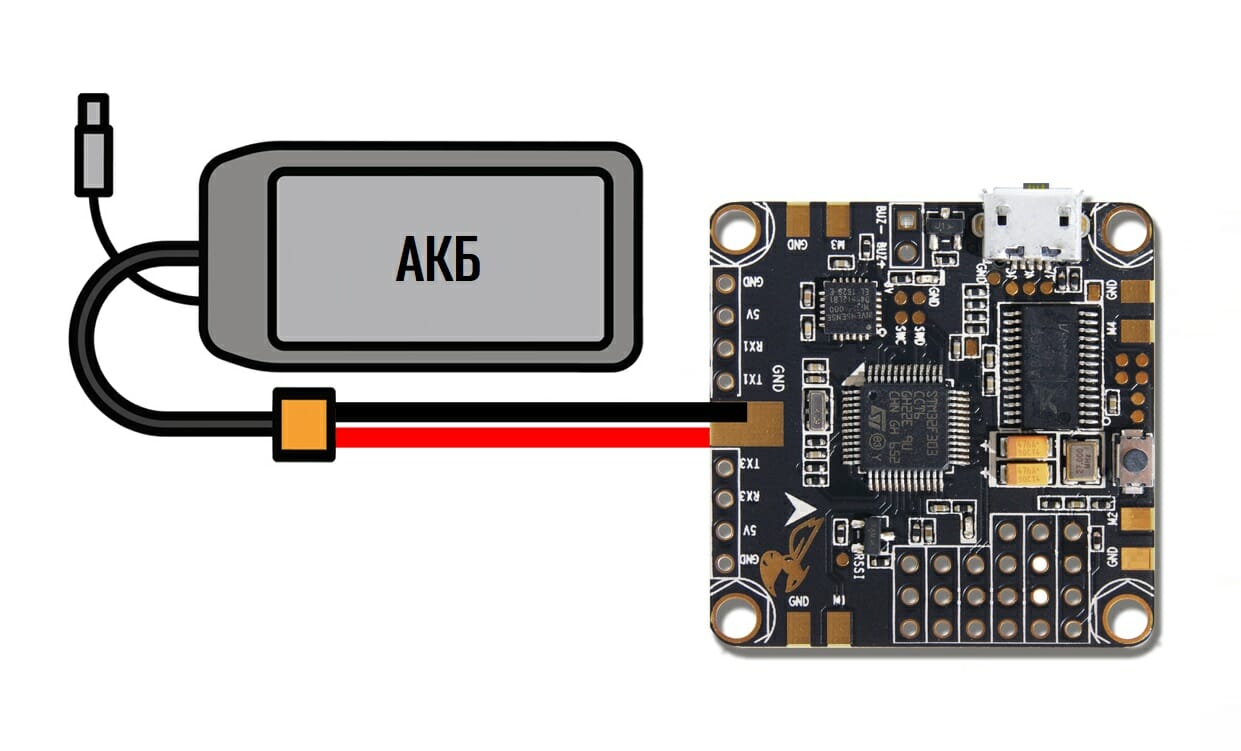
Often, flight controller specifications describe two voltage ranges, the first of which is the input voltage range of the flight controller itself (most operate at rated voltage 5V), and the second is the input voltage range of the main microprocessor (3.3V or 5V). Since the flight controller is an embedded device, you only need to pay attention to the controller's input voltage range. Most multi-rotor UAV flight controllers operate at 5V, as this voltage is generated by the BEC (see section " Powerplant" for more information).
Let's repeat. Ideally, there is no need to power the flight controller separately from the main battery. The only exception is if you need a backup battery in case the main battery is giving off so much power that the BEC cannot generate enough current / voltage, thus causing a power out / reset. But, in this case, capacitors are often used instead of a backup battery.
Sensors
From a hardware point of view, a flight controller is essentially a conventional programmable microcontroller, only with special sensors on board. At a minimum, the flight controller will include a 3-axis gyroscope, but no auto-leveling. Not all flight controllers are equipped with the following sensors, but they can also include a combination of them:
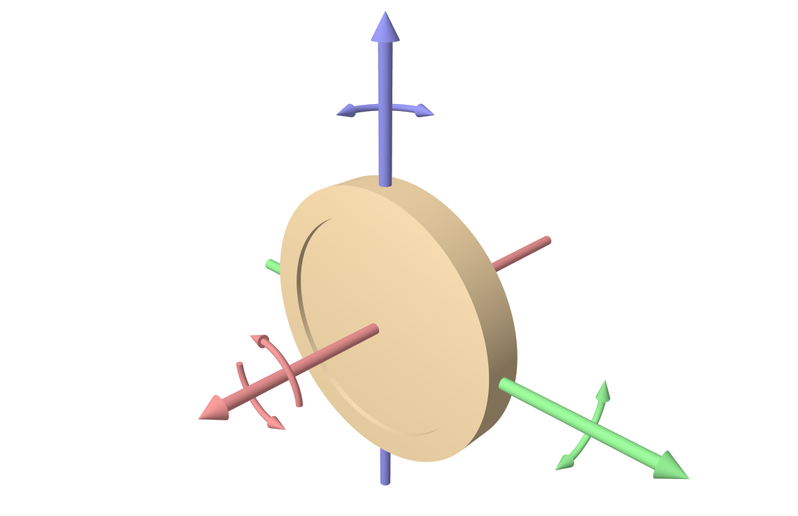
- Accelerometer: As the name suggests, accelerometers measure linear acceleration in three axes (let's call them: X, Y and Z). Usually measured in "G (in Russian. Same)". The standard (normal) value is g = 9.80665 m / s². To determine the position, the output of the accelerometer can be integrated twice, although due to losses at the output, the object may be subject to drift. The most significant characteristic of three-axis accelerometers is that they register gravity, and as such, they can know which direction to "descend". This plays a major role in ensuring the stability of the multi-rotor UAV. The accelerometer must be mounted on the flight controller so that the linear axes coincide with the main axes of the drone.
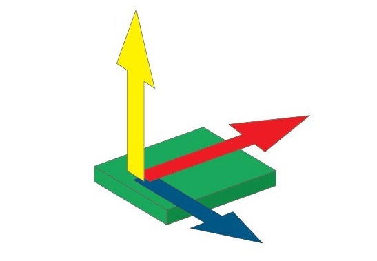
- Gyroscope: The gyroscope measures the rate of change of angles along three angular axes (let's call them: alpha, beta and gamma). Usually measured in degrees per second. Note that the gyroscope does not measure absolute angles directly, but you can iterate to get an angle that, like the accelerometer, encourages drift. The output of a real gyroscope tends to be analog or I2C, but most of the time you don't need to worry about this, as all the incoming data is processed by the flight controller code. The gyroscope must be installed so that its axis of rotation coincides with the axis of the UAV.
- Inertial Measurement Unit (IMU): The IMU is essentially a small board that contains both an accelerometer and a gyroscope (usually multi-axis). Most of these include a three-axis accelerometer and a three-axis gyroscope, others may include additional sensors, such as a three-axis magnetometer, providing a total of 9 measurement axes.
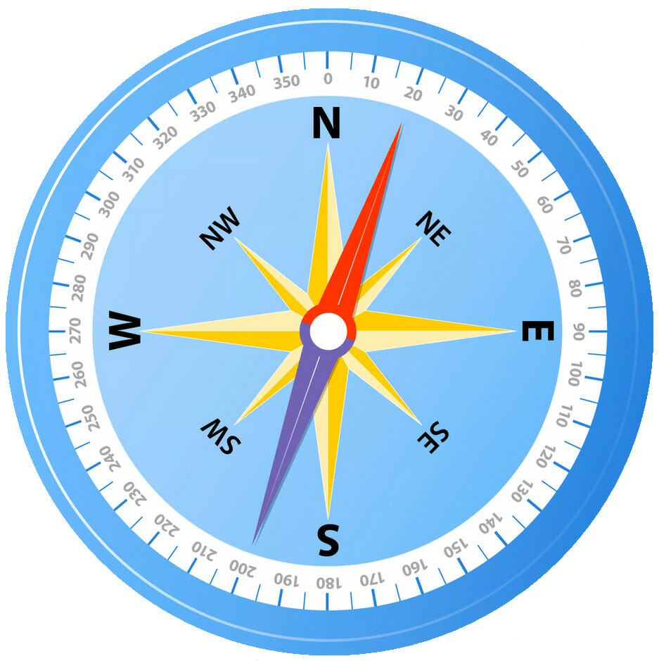
- Compass / Magnetometer: An electronic magnetic compass capable of detecting the Earth's magnetic field and using this data to determining the direction of the drone's compass (relative to the magnetic north pole). This sensor is almost always present if the system has a GPS input and is available from one to three axes.
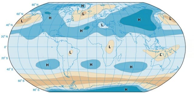
- Pressure / Barometer: Since atmospheric pressure changes with distance from sea level, you can use a pressure sensor to get a fairly accurate readout of the UAV's altitude. To calculate the most accurate altitude, most flight controllers receive data simultaneously from a pressure sensor and a satellite navigation system (GPS). When assembling, note that it is preferable to cover the hole in the barometer body with a piece of foam rubber to reduce the negative effect of wind on the chip.
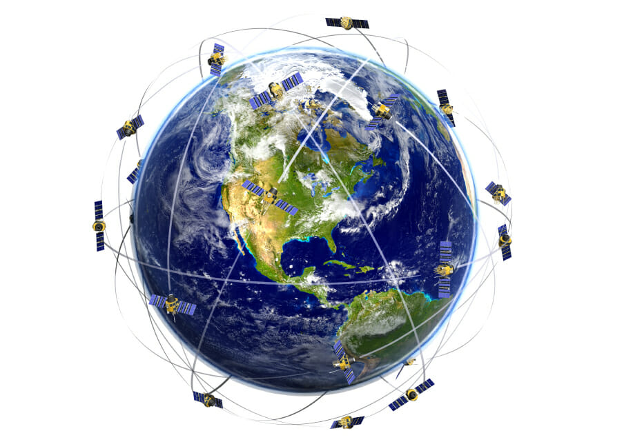
- GPS: Global Positioning System (GPS) to determine your specific geographic location, uses signals sent by several satellites orbiting the Earth. The flight controller can have both a built-in GPS module and a cable-connected one. The GPS antenna should not be confused with the GPS module itself, which can look like a small black box or a regular “Duck” antenna. To get accurate location data, the GPS module must receive data from multiple satellites, and the more the better.
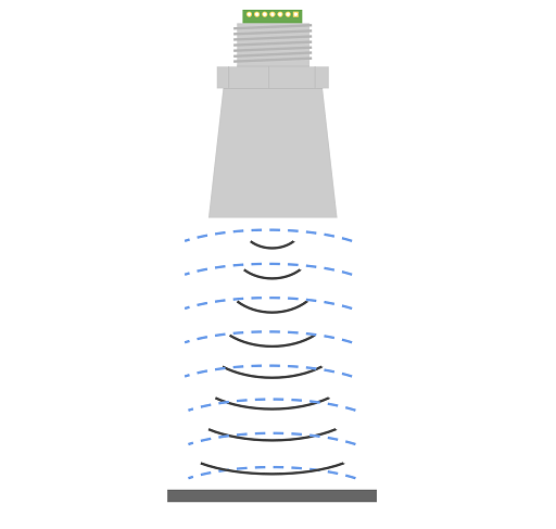
- Distance: Distance sensors are increasingly used on drones as GPS coordinates and pressure sensors cannot tell you how far you are from the ground (hill, mountain or building), or whether you will collide with an object or not. The downward facing distance sensor can be based on ultrasonic, laser or lidar technology (IR sensors may experience problems in sunlight). Distance sensors are rarely included as standard with a flight controller.
Flight modes
Below is a list of the most popular flight modes, however, not all of them may be available in flight controllers... "Flight mode" is the way in which the flight controller uses sensors and incoming radio commands to stabilize and fly the UAV. If the control equipment used has five or more channels, the user can configure the software, which will allow him to change modes through channel 5 (auxiliary switch) directly during the flight.
- ACRO - usually the default mode, of all available sensors, the flight controller uses only the gyroscope (the drone cannot automatically level itself). Relevant for sports (acrobatic) flight.
- ANGLE - stable mode; of all available sensors, the flight controller uses a gyroscope and an accelerometer. The angles are limited. Will keep the drone in a horizontal position (but not hold the position).
- HORIZON - combines the stability of the "ANGLE" mode, when the sticks are near the center and move slowly, and the acrobatics of the "ACRO" mode when the sticks are at their extreme positions and move quickly. The flight controller only uses the gyroscope.
- BARO (Altitude Hold) - stable mode; of all available sensors, the flight controller uses a gyroscope, an accelerometer and a barometer. The angles are limited. The barometer is used to maintain a certain (fixed) altitude when no commands are given from the control equipment.
- MAG (Heading Hold) - heading lock mode (compass direction), the drone will keep Yaw orientation. Of all the available sensors, the flight controller uses a gyroscope, an accelerometer and a compass.
- HEADFREE (CareFree, Headless, Headless) - eliminates the orientation tracking (Yaw) of the drone and thus allows you to move in 2D direction according to movement ROLL / PITCH control stick. Of all the available sensors, the flight controller uses a gyroscope, an accelerometer and a compass.
- GPS / Return to Home - Automatically uses compass and GPS to return to takeoff location. Of all the available sensors, the flight controller uses a gyroscope, an accelerometer, a compass, and a GPS module.
- GPS / Waypoint - allows the drone to autonomously follow preset GPS points. Of all the available sensors, the flight controller uses a gyroscope, an accelerometer, a compass, and a GPS module.
- GPS / Position Hold - holds current position using GPS and barometer (if available). Of all the available sensors, the flight controller uses a gyroscope, an accelerometer, a compass, and a GPS module.
- Failsafe - if no other flight modes have been specified, the drone switches to Acro mode. Of all the available sensors, only the gyroscope is used by the flight controller. Relevant in case of failures in the software of the drone, it allows you to restore control over the UAV using previously preset commands.
Software
PID controller (assignment and setting)
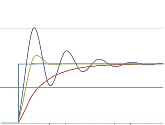
Proportional Integral Derivate (PID) or Proportional-Integral-Derivative (PID) is a piece of flight controller software that reads data from sensors and calculates how fast the motors must rotate to keep the UAV moving at the desired speed.
Developers of ready-to-fly UAVs tend to optimally tune the PID controller parameters, which is why most RTF drones are perfectly piloted right out of the box. What can not be said about custom UAV assemblies, where it is important to use a universal flight controller suitable for any multi-rotor assembly, with the ability to adjust PID values until they meet the required flight characteristics of the end user.
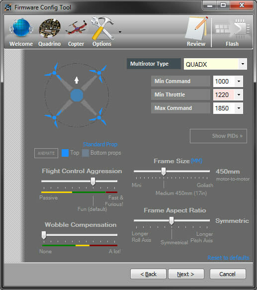
GUI
Graphical User Interface (GUI) or Graphical User Interface Is what is used to visually edit the code (using a computer) that will be loaded into the flight controller. The software that comes with flight controllers keeps getting better and better; the first flight controllers used mostly text-based interfaces, which required users to understand almost all of the code and change specific sections to suit the project. Recently, the GUI has been using interactive graphical interfaces to make it easier for the user to configure the necessary parameters.
Additional features
The software used on some flight controllers may have additional features that not available to others. The choice of a particular flight controller may ultimately depend on what additional features / functionality are offered by the developer. These functions may include:
- Autonomous Waypoint Navigation - Allows the user to set GPS waypoints that the drone will follow autonomously.
- Oribiting - movement of the drone around a given GPS coordinate, where the front of the drone is always directed towards the given coordinate (relevant for shooting).
- Follow me - many UAVs have a “Follow Me” function, which can be based on satellite positioning (for example, tracking the GPS coordinates of a smartphone, or a module built into the control equipment GPS).
- 3D Image - Most 3D images are taken after flight using images and GPS data acquired during flight.
- Open Source - The software of some flight controllers cannot be changed / configured. Open source products generally allow power users to modify the code to suit their specific needs.
Communications
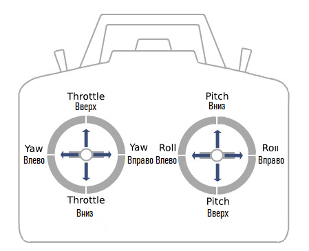
Radio Control (RC)
Radio control typically includes RC transmitter / RC transmitter (in unmanned hobby - radio control equipment / remote control) and RC receiver (RC receiver)
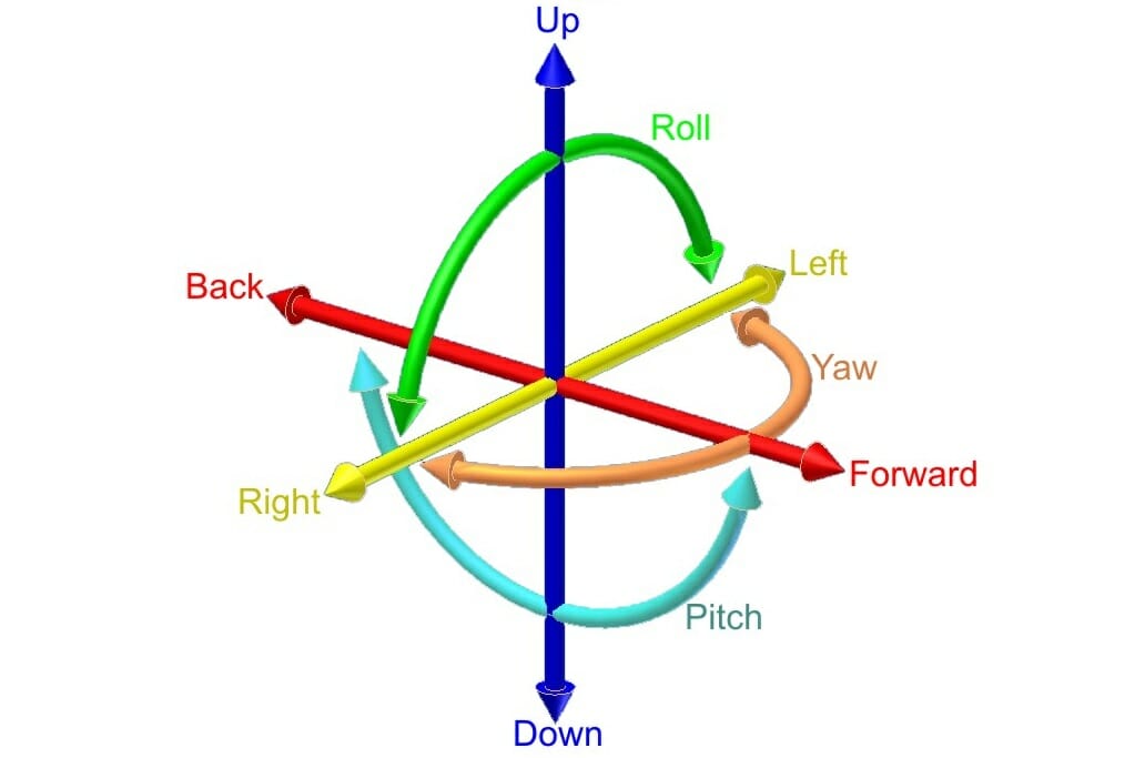
- Throttle / Elevation
- Yaw
- Pitch
- Roll
All other available channels can be used for such actions as:
- Arming (Arming or Arm) / Disarming (Disarming or Disarm) - arming / disarming motors...
- Gimbal control (pan up / down, rotate clockwise / counterclockwise, zoom)
- Change flight modes (ACRO / ANGLE, etc.)
- Activate / engage payload (parachute, buzzer or other device)
- Any other use
Most users (UAV pilots) prefer manual control, this proves once again that piloting with control equipment is still the number one choice. By itself, the RC receiver simply transmits the values coming from the RC transmitter, which means it cannot control the drone. The RC receiver must be connected to a flight controller, which in turn must be programmed to receive RC signals. There are very few flight controllers on the market that accept incoming radio commands from the receiver directly, and most PCs even provide power to the receiver from one of the pins. Additional considerations when choosing a remote control include:
- Not all RC transmitters can provide the full range of RC signals from 500ms to 2500ms; some artificially limit this range, as most RCs in use are for radio controlled cars, airplanes and helicopters.
- Range / Max. air range (measured in feet or meters) RC systems-are almost never provided by manufacturers, as this parameter is influenced by many factors such as noise, temperature, humidity, battery power and others.
- Some RC systems have a receiver that also has a built-in transmitter for transmitting data from the sensor (eg GPS coordinates), which will then be displayed on the LCD of the RC transmitter.
Bluetooth
Bluetooth and later BLE (Bluetooth Low Energy) products were originally intended to transfer data between devices without pairing or frequency matching. Some commercially available flight controllers can send and receive data wirelessly over a Bluetooth connection, making it easier to troubleshoot in the field.

Wi-Fi
Wi-Fi control is usually achieved through a Wi-Fi router, computer (including laptop, desktop, tablet) or smartphone. Wi-Fi is able to cope with both data transmission and video streaming, but at the same time, this technology is more difficult to configure / implement. As with all Wi-Fi devices, the distance is limited by the Wi-Fi transmitter.

Radio frequency (RF or RF)
Radio frequency (RF) control in this context refers to wireless transferring data from a computer or microcontroller to an aircraft using an RF transmitter / receiver (or dual-band transceiver). Using a conventional RF unit connected to a computer allows two-way communication over long distances with high data density (usually in serial format).
Smartphone
Although this is not a type of communication, the question itself is how to control a drone using a smartphone, enough to give it a separate section. Modern smartphones are essentially powerful computers that, coincidentally, can also make phone calls. Almost all smartphones have built-in Bluetooth as well as WiFi, each of which is used to control the drone and / or receive data and / or video.
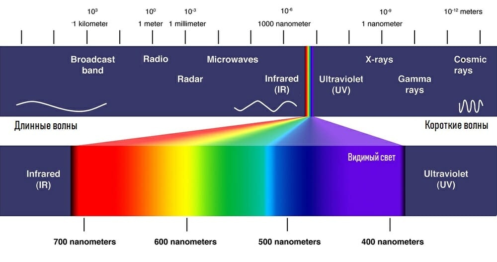
Infrared (IR)
TV remote control) is rarely used to control drones, as even in ordinary rooms (not to mention open spaces) there is so much infrared interference that it is not very reliable. Despite the fact that the technology can be used to control UAVs, it cannot be offered as the main option.
Additional considerations
Functionality: Flight controller manufacturers usually try to provide as many functions as possible - are either included by default or purchased separately as options / add-ons. Below are just a few of the many additional features you might want to take a look at when comparing flight controllers.
Damping: Even small vibrations in the frame, usually caused by unbalanced rotors and / or motors, can be detected by the built-in accelerometer, which in turn will send the appropriate signals to the main processor, which will take corrective action. These minor fixes are unnecessary or undesirable for stable flight, and it is best to keep the flight controller vibrating as little as possible. For this reason, vibration dampers / dampers are often used between the flight controller and the frame.
Enclosure: The protective enclosure around the flight controller can help in a variety of situations. In addition to being more aesthetically pleasing than a bare PCB, an enclosure often provides some level of electrical protection. elements, as well as additional protection in the event of a crash.
Mounting: There are various ways to mount the flight controller to the frame, and not all flight controllers have the same mounting options:
- Four holes at a distance of 30.5mm or 45mm from each other squared.
- Flat bottom for use with a sticker.
- Four holes in a rectangle (standard not installed).
Community: Since you are building a custom drone, participating in an online community can help a lot, especially if you run into problems or want advice. Getting advice from the community or viewing user feedback regarding the quality and ease of use of different flight controllers can also be helpful.
Accessories: For the full use of the product, in addition to the flight controller itself, you may need related items (accessories or options). Such accessories may include, but are not limited to: GPS module and / or GPS antenna; cables; mounting accessories; screen (LCD / OLED);
Example
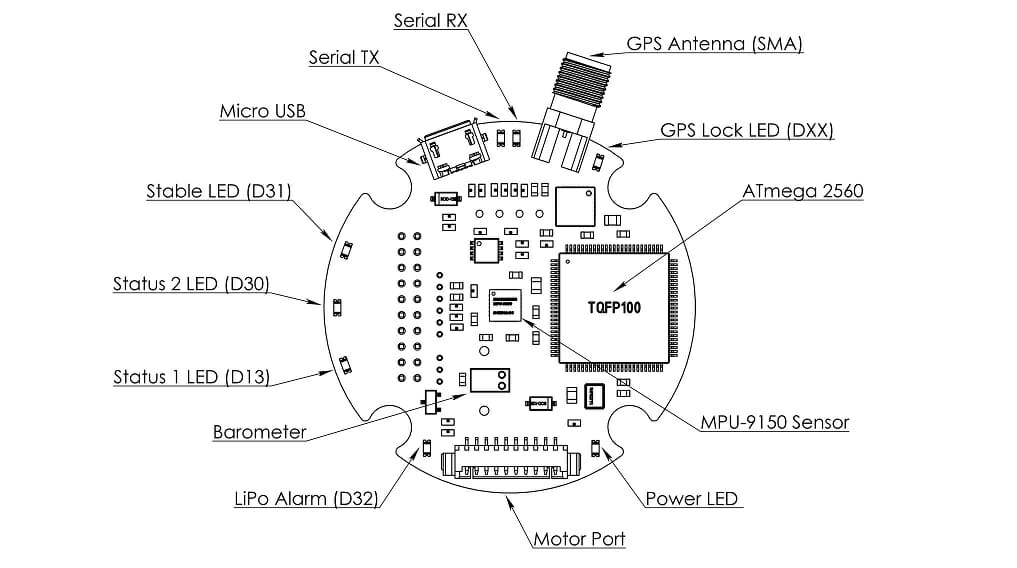
So with all these different comparisons, what information can you get about the flight controller and what might the flight controller include? We have chosen Quadrino Nano Flight Controller
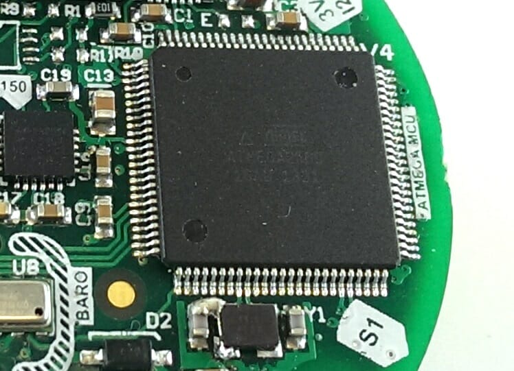
Main Processor
Used onboard ATMel ATMega2560 is one of the most powerful Arduino-compatible ATMel chips. Although it has a total of 100 pins, including 16 analog-digital channels and five SPI ports, due to its small size and intended use as a flight controller, only a few of them are present on the board.
- AVR vs PIC: AVR
- Processor: 8-bit
- Operating frequency: 16MHz
- Program memory / Flash: 256KB
- SRAM: 8KB
- EEPROM: 4KB
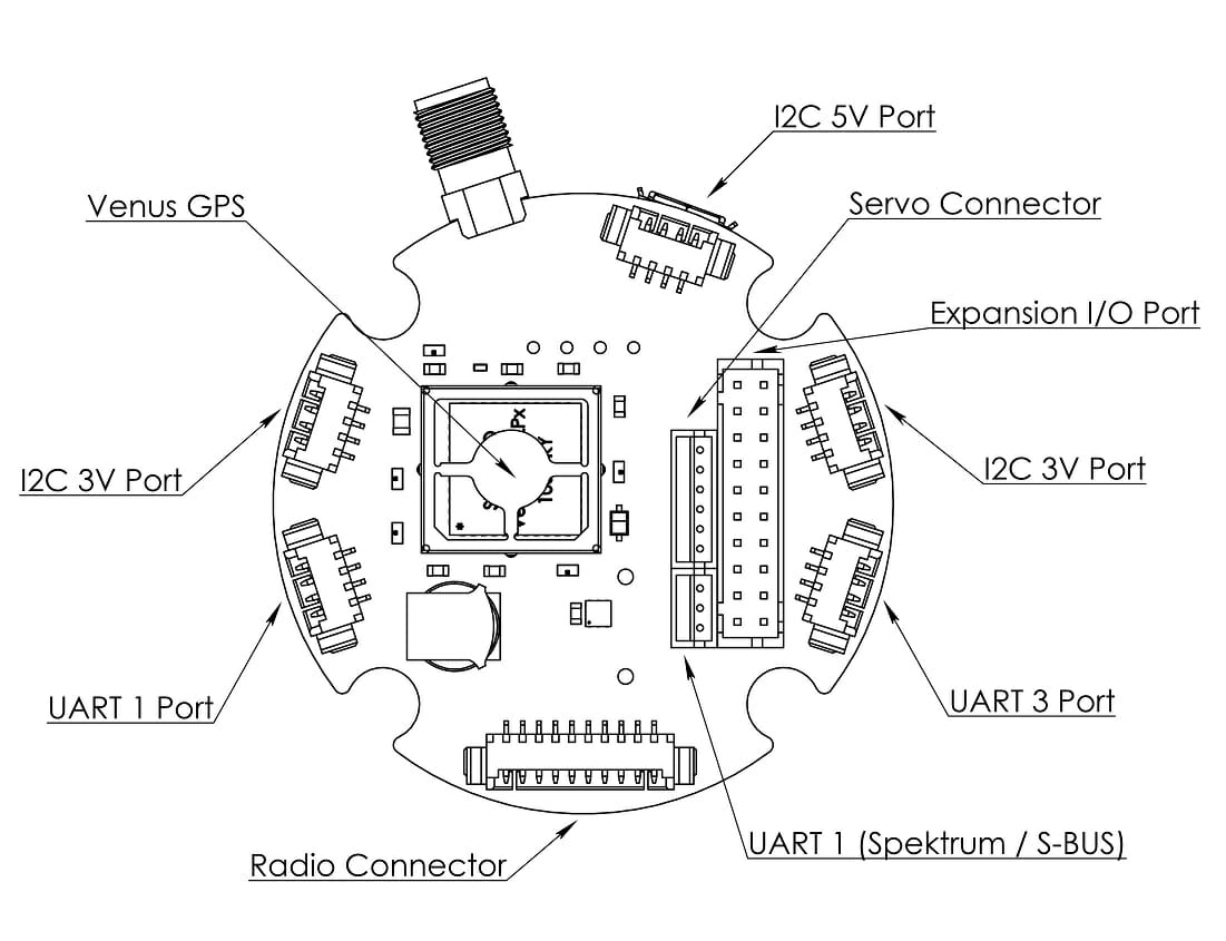
- Additional I / O pins: 3 × I2C; 1 × UART; 2 × 10-pin GPIOs; Servo with 5x outputs; OLED port
- A / D converter: 10-bit
Sensors
Quadrino Nano includes the MPU9150 IMU chip, which includes a 3-axis gyroscope, a 3-axis accelerometer and a 3-axis magnetometer. This helps keep the board small enough without sacrificing sensor quality. The MS5611 barometer provides pressure data and is covered with a piece of foam. Integrated Venus 838FLPx GPS with external GPS antenna (included).
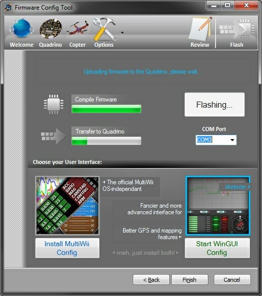
Software
The Quadrino Nano was built specifically to use the latest MultiWii software (based on Arduino). Instead of modifying the Arduino code directly, a separate, more graphical software was created.
Communication
- Direct input from standard RC receiver.
- Dedicated Spektrum Satellite Receiver Port
- Serial (SBus and / or Bluetooth or 3DR radios)
.Additional Factors
- Enclosure: Protective translucent enclosure included as standard
- Mounting: There are two main ways of attaching the Quadrino Nano to drone: screws and nuts or foam rubber sticker.
- Compact design: the controller itself (excluding the GPS antenna) measures 53x53mm.