Contents
- DIY drone: Lesson 1. Terminology.
- Do-it-yourself drone: Lesson 2. Frames.
- Do-it-yourself drone: Lesson 3. Power plant.
- Do-it-yourself drone: Lesson 4. Flight controller.
- Do-it-yourself drone: Lesson 5. Assembly.
- Do-it-yourself drone: Lesson 6. Performance check.
- Do-it-yourself drone: Lesson 7. FPV and distance.
- Drone with your own hands: Lesson 8. Airplanes.
Introduction
Now that you have selected all the main components for your UAV, you can start assembling. This guide will cover common mistakes when assembling a multi-rotor UAV, as well as provide some helpful tuning tips. This lesson will not cover items such as a camera / FPV system, long range devices or other accessories (we will look at it in lesson 7).
Components you must have at this stage:
- Frame (purchased or handcrafted)
- Motors, ESCs, propellers, battery, charger device
- Power distribution board / harness
- Flight controller and communication device (radio control proposed)
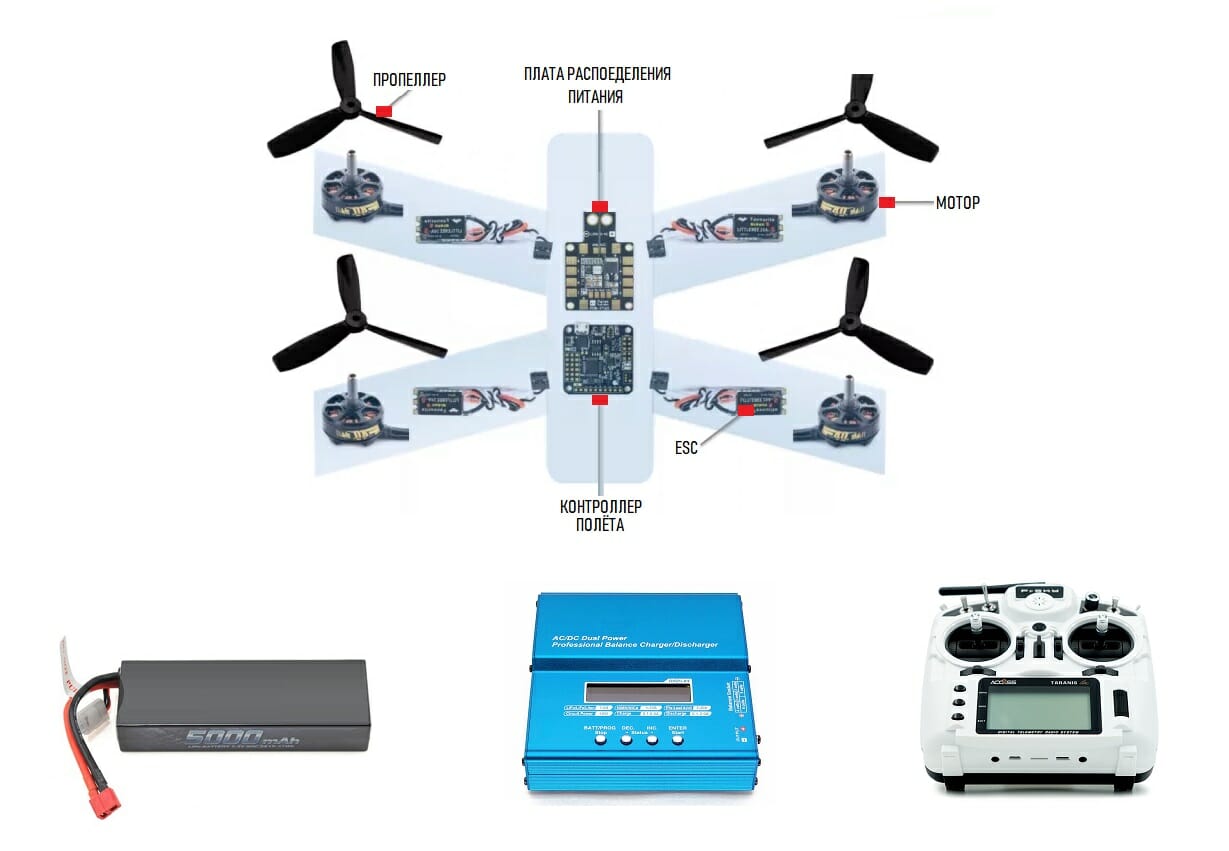
Propulsion
To achieve the objectives of this lesson, your UAV's propulsion system will include the following components:
- Motors
- ESC
- Power Distribution (board or harness)
- Battery
- Flight Controller
Note that propellers are not listed. Do not install propellers at this stage! The main screws will be connected only in the 6th lesson. Since this is your first drone, we recommend making a “frameless” electrical connection before installing everything on the frame; in order to check all connections and eliminate the identified faults.
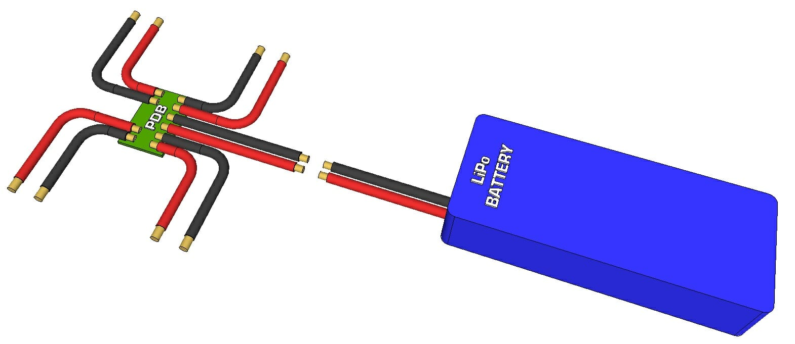
Battery. Power Distribution
The connection between the battery and the power distribution system should be relatively simple if they both have the same connector type. If so, then proceed to the next step. If the connectors are different, then in no case cut the battery wires to separate the connector; this can cause a short circuit and an unpleasant electric shock! Instead, you can pick up an adapter and use it between the connector on the battery and the connector on the power distribution board. Another option may be to search for a mating connector to the battery connector, and buy it; then cut the existing connector from the power distributor and solder the purchased replacement, making sure that there is no connection between the positive and negative pins.
It is important to note that most multi-rotor UAVs do not have an on / off switch, so power is supplied and disconnected by connecting and disconnecting the main battery from the power distributor connector, so their connectors must be securely fastened and the wires / solder points are good insulated with heat shrink tubing and / or electrical tape.
Disconnect the battery from the power distributor before proceeding.
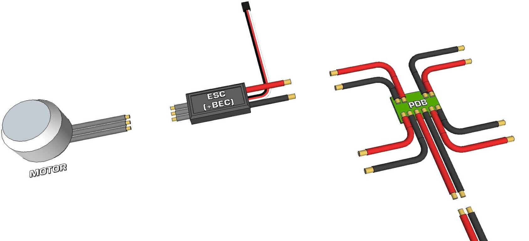
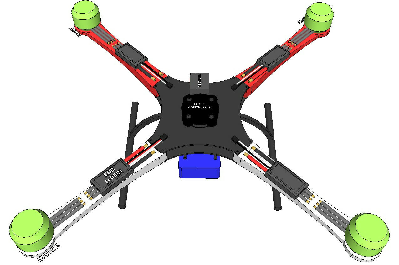
Motor. ESC. Power Distribution
The Power Distribution Board (PDP) or wired distribution primarily serves to distribute power from the main battery to each ESC. The voltage is supplied to the ESC as is, so there is no need to increase (increase) or decrease (decrease) the voltage. If your drone has four motors, then you should have four ESCs, and therefore your distribution board / wire distribution should eventually split the main battery into four connections. If your PRP has six connections, and you are building a quadrocopter, then you simply do not need to connect the last two. If you are building a hexacopter, your PDP should distribute power from the main battery to six connections. The ESC includes the following wires:
- One 3-wire 0.1-inch ribbon with R / C connector, of which the black pin is usually ground, the red one provides 5V output (via BEC*) and yellow / white is the signal input.
- Three separate wires connect to the three wires on a brushless DC motor (usually supplied with female bullet connectors that are either already soldered or included).
- Two input connectors for connecting the battery to the PDB (some include soldered connectors with soldering, some are included, and sometimes not at all).
*ESCs usually have a built-in battery elimination circuit (or BEC) that converts the main battery voltage to 5V for powering the receiver and flight controller. 5V is usually supplied via the RC connector from the ESC (usually the center / red pin). You only need one BEC to power the flight controller.
If the power distribution board uses connectors that do not match the connectors on the ESC or battery, then you will need to either purchase adapters (adapters), or purchase new connectors and replace them on ESC or PRP. The advantage remains with the power distribution board, the connectors of which match those of the battery and ESC. Most often, a lithium-polymer battery of a UAV can have DEANS connectorXT60EC3
If you want to power additional low-current electronics (LED lighting, pendant, etc.) but there are no spare connections on your power distribution board, you can use the battery charging cable. The white charging connector usually has one pin for ground and one pin for each cell (1S, 2S, 3S, etc.) used in the LiPo battery assembly. Although this connector is really only for charging the battery, it can provide a 3.7V output voltage from each pin and can be used to power low-current electronics such as a harness or LEDs.
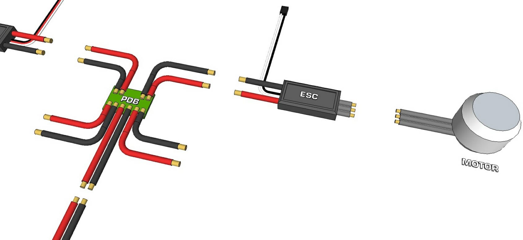
- Remove the red lead from every 3-pin R / C connector of the cruise control except one. It is recommended that you do this in such a way that you can always plug them back in if necessary. Wrap the end of each excluded wire with electrical tape or use heat shrink tubing for insulation so that later they cannot come into contact with other electronics. The only red wire that is left untouched will power the flight controller used in the assembly.
- Connect the two supply wires of each ESC to the distribution board, making sure the red wire goes to positive () and the black wire to negative (-).
- If the power distribution board you are using has its own R / C connectors, then in this case it is up to you to connect the R / C pins of each ESC to the R / C connectors on this board or connect them directly to the flight controller.
- Connect each of the three motor connectors to the three ESC connectors. At the moment, the order of connecting these connectors is not important (if it affects the direction of rotation, it will be corrected as necessary later).
Please note that if you decide to remove or hide the wiring at this stage, you may later need to access some of the connections in accordance with the procedure described in Lesson 6, in particular, swap the connections between the ESC and a motor so that the motor rotates in the opposite direction.
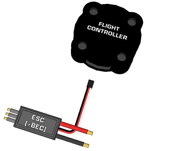
ESC. Flight controller.
You can now connect the R / C inputs of the cruise controllers to the flight controller. The flight controller you choose should have a diagram that shows which controller pins are connected to the motors of your multi-rotor assembly. This diagram should also show the direction of rotation of each motor, but again, you don't need to consider the direction for now.
- See the connection diagram between the motors / ESC and the flight controller in the PC instruction manual.
- Connect the R / C connectors of each ESC to the corresponding pins on the flight controller, make sure the ground wire (usually black) connects to the ground pin of the flight controller and the signal pin (white or yellow) connects to the signal pin on the flight controller...
- Only one of the RC connectors will still have the red (power) pin.
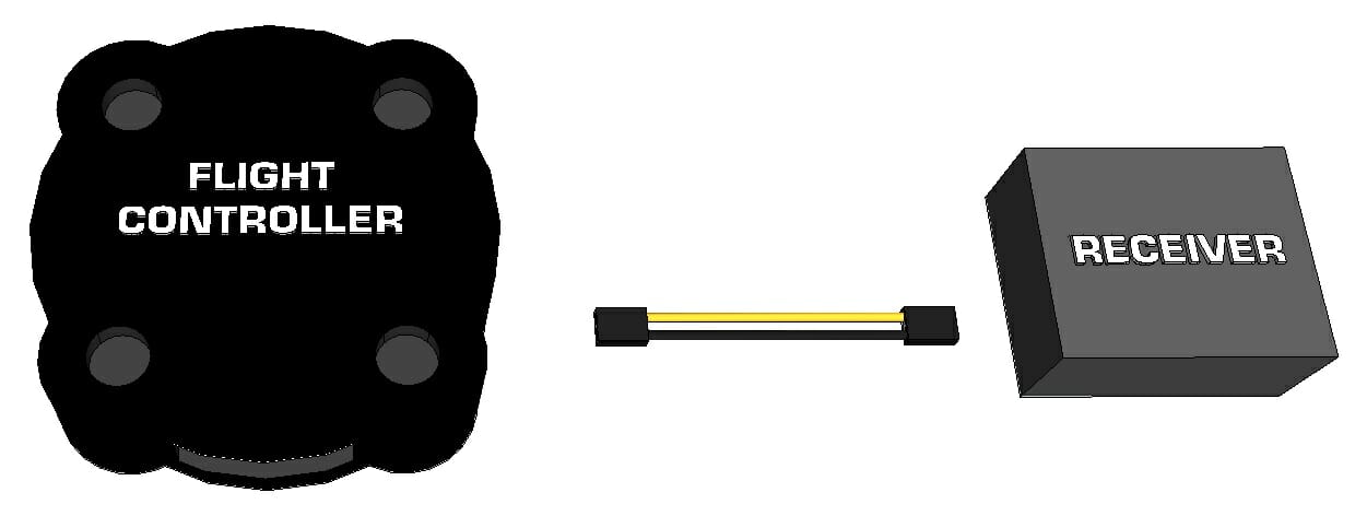
Communication
Receiver. Flight controller.
Suppose that in this lesson you have made the choice in favor of radio control as the input device. If you want to use WiFi, Bluetooth or other input method, please read the flight controller manual and search for serial input; This section will describe how / where to connect the serial input device to the flight controller. You will most likely need to find and connect the transmit (Tx), receive (Rx), voltage (5V), and GND pins from the wireless device to the transmitter, allowing Rx from one to the other's Tx, and vice versa.
Your RC transmitter must come with an appropriate RC receiver. The receiver must be bound to the transmitter so that you can remove the bind jumper from the receiver (if any). The kit may also include an AA battery holder, which is designed to power the receiver, but we will not use it as the BEC will power both the receiver and the flight controller. To find out which RC receiver channels connect to which pins on the flight controller, you need to look at the user manual of both the flight controller and the RC system.
The flight controller manual will indicate the locations of the following pins to be matched and connected to the receiver:
- Throttle
- Pitch
- Yaw
- Roll
- Aux Switches 1, 2, 3, etc.
You can now make the following connections:
- Read the flight controller manual to see which R / C input pin is connected with which of the above functions.
- Read the transmitter manual for which channel is associated with each function.
- Some RC transmitters can be reprogrammed to change the function of each contact. If you decide to change any input (joystick or switch), do so only after making sure you know which channel on the receiver corresponds to which function. Throttle, Pitch, Yaw, and Roll should always be associated with two sticks / joysticks, not switches or buttons.
- Connect the Throttle channel on the receiver to the Throttle input on the flight controller.
- Connect the Pitch channel on the receiver to the Pitch input on the flight controller.
- Connect the Yaw channel on the receiver to the Yaw input on the flight controller.
- Connect GND on the flight controller (usually the third row of pins) to GND on the receiver (usually the third row of pins).
- If the auxiliary input will be used, connect Aux 1 on the receiver to Aux 1 on the flight controller, and so on.
You can use 3-pin servo wires for each channel, but only one of the channels (can be any) must have voltage and ground; the rest only need a signal wire. All connections can be GND to GND, although only one is required. Once again, the receiver does not need a separate battery as it will be powered by the flight controller, which is powered by the BEC from one of the ESCs.
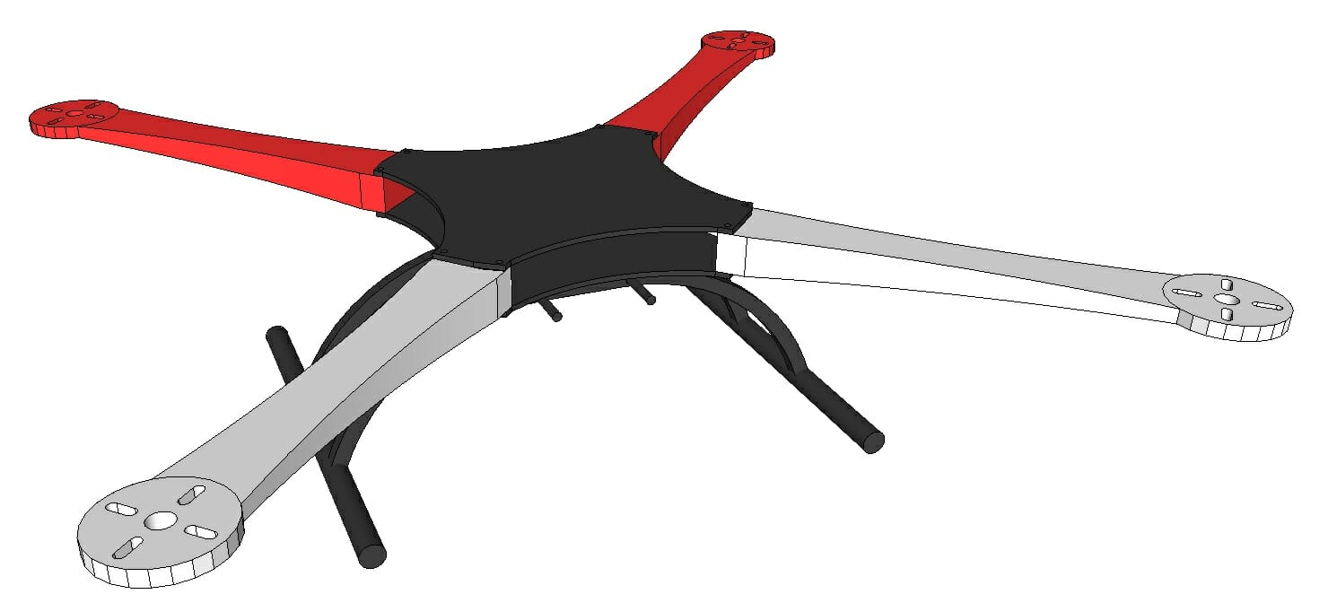
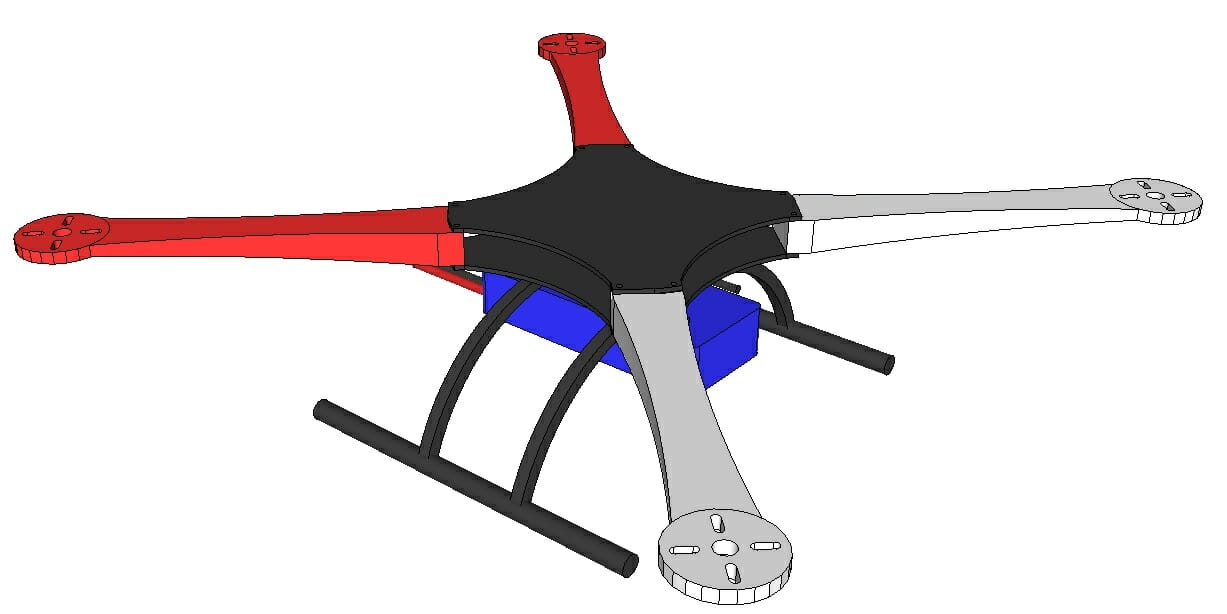
Assembling the Frame
If you are building your own frame, you can assemble it at this stage. If you purchased a frame kit, follow the assembly instructions. Please note that you may need to disassemble certain areas in order to facilitate connection or remove (hide) electrical elements. The goal is to ensure that nothing is loosened, all wires are securely fastened, and nothing can fall out of the frame or get tangled.
Installation
Battery location.
The battery used for power is often the heaviest element on a UAV and can range from 1/4 to 1/2 of its total weight. Therefore, the place of its installation is very important. The ideal location for the main battery should be in the center of the aircraft so that all motors can handle roughly the same load. If the battery is located closer to the rear of the aircraft, the rear motors will have to provide more thrust than the front motors, and therefore the maximum total thrust will be limited (when the rear motors are at full thrust, there will be no thrust on the front motors). Whereas, the usual approach in multi-rotor design is to keep the aircraft symmetrical about a centerline (or at least one axis), so the battery should be placed along that centerline rather than offset to one side or the other...
Next, you will need to decide at what height to place the battery. There are several places where the battery can be installed:
- Under the frame (the aircraft will be heavy on the bottom, more stable and less acrobatic).
- Directly under the motors (usually inside the frame); possibly one of the best places.
- At the same height as the engines or rotors (eg mounted on top of the frame).
- Above the propellers (the UAV will be heavier on top and more prone to flipping).
For best performance, ideally the battery should be located in position 3 above. Position 4 creates the effect of an inverted pendulum, and if the UAV tilts beyond a certain angle, the drone will tend to flip. Position 1 will create a fairly stable platform that by its nature tends to stay level, but is extremely unsuitable for acrobatics. Therefore, most designers choose position 2 and place the battery either directly under the frame or inside it. This approach frees up space under the frame for payloads like the suspension system, and space above for the flight controller and other electronics to be as accessible as possible.
Battery Mounting
There are many common ways of attaching the battery to the frame, including:
- Velcro straps
- Self-adhesive Velcro (one side is glued to the battery and the other to the frame)
- In the frame
Velcro straps are most common for medium “standard” size custom drones While frame enclosure is most commonly found on commercial drones, the frames of such UAVs are conceived under pressure and leave space inside specifically for a specific battery. Velcro should ideally only be used if the battery is relatively light; instead of one short section in the center, it is recommended to glue one strip along the entire length of the battery. If you are using Velcro straps and find that the battery tends to pop out due to lack of grip, it is recommended that you add rubber strips where the battery contacts the straps. It is not recommended to use glue to secure the battery to the frame. If you are not using a UAV, remove the battery and store it in a LiPo safe bag or ceramic reservoir.
Charging the battery
It is very likely that you have chosen a Lithium Polymer (LiPo) or other lithium battery. Most LiPo batteries over 3.7V have a separate charging cable with a multi-pin connector for charging, while the power cable can be identified by the presence of a two-pin connector with larger wires capable of withstanding high discharge currents. A charging connector usually has one contact for each battery bank, as well as a common ground contact.
Due to the dangers associated with LiPo batteries (hydrogen and electricity), it is common practice to completely remove the battery from the drone when not in use and place it in a LiPo Safe bag. The same bag is used when charging the battery (connect the battery to the charger, place the battery in the bag (leaving the charger outside the bag) and close it (it usually has a Velcro flap).
.Flight Controller Placement and Mounting
Ideally, the flight controller should be located in the center of the drone at the same height as the motors. If this is not possible, then the controller can be placed slightly higher or lower. direction to the left or right, and avoid mounting it forward or backward. If you purchased a frame for a UAV, these often have mounting holes for the flight controller, which are in the optimal place. The flight controller can be fixed in any of the following basic ways:
- Screws / Nuts / Uprights (basic)
- Double-sided tape (make sure it is strong enough)
- Double-sided foam tape (to achieve damping effect)
- Rubber damping bushings (for high damping)
Some flight controllers either have or may have an optional protective case.
At this stage you should have a fully assembled and connected UAV, excluding the propellers. Lesson 6 includes setting up and testing the transmitter, flight controller software, pre-flight check and first flight.


